

WiFi 6 Router Network Deployment Solutions
Five Typical Scenarios · Product Selection Guide · Network Topologies · Installation and Acceptance · Quote Templates
Key Points of Wi-Fi 6 Technology
OFDMA, MU-MIMO, TWT, BSS Coloring, and Bandwidth Baseline
Construction and Radio Frequency Specifications
Cabling, Channels, Power, Roaming, and Acceptance Criteria
Overview of Solution Selection
Comparison of Area, Cabling Requirements, Device Capacity, and Roaming Capabilities
Frequently Asked Questions and Risks
Double NAT, Return Path Loss, PoE Power Supply, and Interference Avoidance
Five Networking Solutions
Single-Router / Wired Mesh / Wireless Mesh / AC+ Panel / AC+ Ceiling Mount
Quote Template
Summary of Equipment, Materials, Construction, Commissioning, and Costs
Technical Highlights
The value of Wi-Fi 6 lies in its efficiency with multiple concurrent connections, not in its nominal peak data rate.
| OFDMA | Channel division into resource units enables parallel transmission of small packets by multiple terminals, improving concurrent latency in smart home and mobile payment scenarios. |
| MU-MIMO | AP communicates with multiple devices simultaneously, improving uplink and downlink scheduling efficiency in high-density office environments. |
| TWT | The terminal and AP negotiate a wake-up cycle, allowing IoT devices to enter sleep mode to conserve power while reducing air interface occupancy. |
| BSS Shading | Use identifiers to distinguish devices on the same frequency but in different networks, thereby reducing false detections of co-channel interference and unnecessary backoff during dense deployments. |
| Bandwidth Baseline | 80 MHz is the safe choice; 160 MHz should only be enabled in environments with a clean spectrum; actual throughput should be estimated at 60 to 70 percent of the rated value. |
Note: These are estimated engineering figures; actual performance is subject to on-site surveys and measurements.
Model Selection Overview
Determine the layout based on floor area, cabling conditions, and the number of units to be installed to avoid architectural mismatches
|
Plan |
Coverage Area |
Wiring Requirements |
Bring your device |
Roaming |
Recommended for |
|
Option 1 |
≤80㎡ Single-level apartment |
No wiring required |
≤20 units |
Weak |
Small Apartments, Rental Housing, Studios |
|
Option 2 |
120-250㎡ |
Network cables have been pre-installed |
30-80 units |
Excellent |
Users of open-plan apartments, gaming, and NAS |
|
Option 3 |
100-180㎡ |
No Ethernet cable |
20-50 units |
Generally |
Blind Spots in Fully Furnished Homes: Temporary Cover-Ups |
|
Option 4 |
150-300㎡ |
Pre-installed network cables at each location |
60-80 units |
Excellent |
Luxury Residences, Whole-Home Smart Systems |
|
Option 5 |
300-800㎡ |
PoE Cabling |
80-150 units |
Excellent |
Small and micro-enterprises, showrooms, and chain stores |
Selection Principles: Do not force the use of an AC+AP configuration if wiring is not available; do not use a single router in a single-family home setting; if any criterion is not met, select a more robust solution.
Option 1
Compact Single-Unit Wi-Fi 6 Router: Low-Cost, Direct-Connect Coverage

The orange lines represent fiber-optic connections, and the blue lines represent six-wire Ethernet cables; the thick dashed lines represent Mesh wireless backhaul.
Applicable Scenarios
≤80 m² single-level apartment, broadband speed 100 M-1,000 M, ≤20 concurrent devices, no need for cross-room roaming.
Key Configuration Points
- Set the ONT to bridge mode and configure the router for dial-up to avoid double NAT.
- Set the 5 GHz band to 80 MHz; if the environment is clear, you can enable 160 MHz.
- Set the 2.4 GHz band to a fixed 20 MHz with mixed WPA2/WPA3 encryption.
- Place the router in an open, elevated location with ample space around it for heat dissipation.
Acceptance Criteria
- Near-field 5G: ≥800 Mbps; through walls: ≥300 Mbps
- Edge RSSI: ≥ -70 dBm; ping to gateway: <5 ms with no packet loss
Option 2
Wired Mesh for Large Homes: Wired backhaul, seamless roaming with no loss of bandwidth

The orange lines represent fiber-optic connections, and the blue lines represent six-wire Ethernet cables; the thick dashed lines represent Mesh wireless backhaul.
Applicable Scenarios
120–250 square meters, single-level or duplex units, with Category 6 network cabling pre-installed, supporting 30–80 terminals, requiring seamless roaming and low latency.
Key Configuration Points
- Switches are aggregated, and all sub-nodes have wired backhaul.
- The entire network uses the same SSID, and DHCP is disabled on sub-nodes.
- 11k/v/r is enabled, and channels are staggered between adjacent nodes.
- The guest network is completely isolated, and access to the internal network is prohibited.
Acceptance Criteria
- Return link ≥900 Mbps, node near-field ≥600 Mbps
- Handover <50 ms, guests cannot access the internal network
Option 3
Wireless Mesh for Newly Built Homes: No wiring required, eliminates dead zones, but suffers from bandwidth loss on the return path
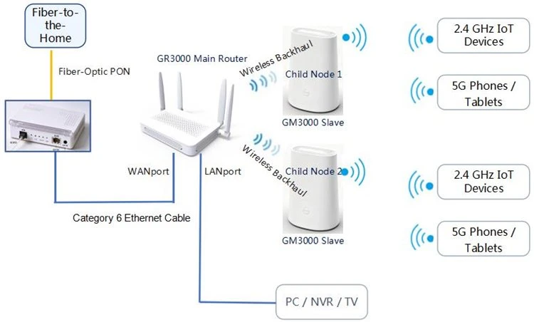
The orange lines represent fiber-optic connections, and the blue lines represent six-wire Ethernet cables; the thick dashed lines represent Mesh wireless backhaul.
Applicable Scenarios
100–180 square meters; fully renovated unit where it is not possible to cut channels for wiring; 20–50 terminals; primarily for coverage and filling in dead zones.
Key Configuration Points
- Prioritize tri-band models; use a dedicated 5G band for backhaul.
- Place child nodes within the -60 to -70 dBm range relative to the main router.
- Disable auto-channel and auto-power; limit the number of nodes to no more than 3.
- Route large file transfers and 4K streaming traffic to the vicinity of the main router.
Acceptance Criteria
- Return path ≥ 50% of the contracted broadband speed; near-field speed at child nodes ≥ 400 Mbps
- No areas with signal levels below -75 dBm; no nodes have been offline for 72 hours
Option 4
Home Automation AC+ Panels AP: Aesthetic and Consistent, with Independent Coverage for Each Room

Solid lines represent wired links; dashed lines represent wireless access; thick dashed lines represent Mesh wireless backhaul.
Applicable Scenarios
150–300 square meters; villas or large open-plan apartments; network cables pre-installed during the electrical and plumbing phase; 60–80 terminals; designed for a clean, uncluttered appearance and centralized management.
Key Configuration Points
- Unified Management and Power Supply via AC+PoE All-in-One Units
- Each location must have an independent network cable running back to the low-voltage distribution box; daisy-chaining is prohibited.
- Panel power: 12–15 dBm, to prevent signal overflow and ping-pong effects.
- Install additional ceiling-mounted APs in the large living room and atrium area.
Acceptance Criteria
- RSSI ≥ -60 dBm indoors, roaming < 50 ms
- ≤ 20 single-band devices; guest isolation is enabled
Option 5
Commercial AC + Ceiling-Mounted AP: High-Density Concurrency, Multi-VLAN Isolation for Operations and Maintenance

Solid lines represent wired links; dashed lines represent wireless access; thick dashed lines represent Mesh wireless backhaul.
Applicable Scenarios
300–800 square meters of office, retail, or showroom space, with 80–150 devices, requiring multiple SSIDs for isolation, authentication, and centralized management.
Key Configuration Points
- Gateway-Core-PoE-Ceiling-Mounted AP Tiered Architecture
- VLAN10 Office / VLAN20 Guest / VLAN30 IoT
- Enable load balancing and connection limits; set 11k/v/r to maximum
- Reserve 1.3 times the peak total PoE power as a margin
Acceptance Criteria
- RSSI ≥ -65 dBm in office areas; 25–35 devices per AP
- Roaming < 50 ms; three-network isolation; 72 hours without disconnection
Construction and Radio Frequency Specifications
Cabling, RF, and Acceptance Testing shall be performed in accordance with a unified baseline.
Key Points for Wiring and Installation
- Set the ONT to bridge mode and use routing for dial-up to avoid port mapping and remote access issues caused by double NAT.
- Use Category 6 unshielded Ethernet cables, with individual runs ≤80 meters; Category 5e is suitable only for short distances to support Gigabit speeds. The low-voltage distribution cabinet should house only the ONT and switch; wireless devices should be located externally, with space reserved for ventilation and heat dissipation.
- RSSI in the overlap zone between adjacent nodes should be maintained between -65 and -70 dBm; do not increase transmit power to compensate for coverage gaps
- Each AP must have its own dedicated Ethernet cable running back to the low-voltage distribution cabinet; daisy-chaining is prohibited
|
Configuration Options |
For Home Use |
Commercial |
|
2.4 GHz bandwidth |
20MHz |
20MHz |
|
5G Bandwidth |
80 MHz, clean environment 160 |
80 MHz; 40 MHz in congested areas |
|
Transmit Power |
16-18dBm |
12-15dBm |
|
Encryption |
WPA2/WPA3 Hybrid |
WPA2/WPA3 or Enterprise |
|
Roaming |
11 kV, on-demand r |
11k/v/r fully open |
Acceptance testing consists of three layers: the link layer tests connectivity and data rates; the wireless layer tests coverage and roaming (handover delay <50 ms); and the service layer tests concurrency and video conferencing continuity.
Frequently Asked Questions and Risks
Most malfunctions are unrelated to the quality of the equipment; they stem from details in planning and construction.
|
Phenomenon |
Common Causes |
Procedures |
|
Gigabit broadband speed test shows only about 300 Mbps |
The ONT is not set to bridge mode, the Ethernet cable is of poor quality, the WAN port is 100 Mbps, and the device is connected wirelessly. |
Change to bridge mode, replace the Category 6 cable, verify the WAN port specifications, and run a wired speed test |
|
Signal is at full strength, but the webpage won't load |
Multiple Routers with the Same SSID Not Configured as a Mesh Network: DHCP Conflict |
Unify the Mesh or switch to AP mode, keeping only one DHCP server |
|
Frequent Disconnections at Night |
Adjacent-Channel Interference, Automatic Channel Switching |
Fixed channel, 2.4 GHz, 20 MHz only, staggered retesting |
|
Child nodes frequently go offline |
The wireless backhaul passes through two load-bearing walls, resulting in a signal strength below -75 dBm. |
Adjust the placement or switch to a wired return path |
|
AP Keeps Restarting |
Insufficient PoE power, poor crimping, overheating of the low-voltage distribution box |
Calculate total PoE power, rework the RJ45 connectors, and improve heat dissipation |
|
Visitors can access the NAS |
The guest network is not isolated, and AP isolation is not enabled. |
Separate VLAN or guest network segment; enable isolation |
Quote Template
The quotation is organized into three sections: equipment and materials, construction and commissioning, and summary of costs.
Equipment and Materials Costs
- Main Router / Enterprise Gateway
- Sub-Mesh Node / AP
- PoE Switch
- AC Controller
- Cat 6 Ethernet Cable, Faceplates, and Modules
- Rack, Cable Management, and Accessories
Construction and Commissioning Costs
- Site-Specific Cabling Installation
- Equipment Installation and Mounting
- System Commissioning and RF Planning
- Link Testing and Documentation
- Work at Heights / Ceiling Work
- Removal and Haul-off of Old Equipment
Summary of Expenses
- Subtotal for Equipment and Materials
- Subtotal for Construction and Commissioning
- Taxes (at the agreed-upon rate)
- Total Price Including Tax (in words)
- Discounts / Rebates
- Final Quote
Unit prices are subject to the manufacturer's current quotation; quantities and unit prices are left blank in the bill of materials template to be filled in later. The validity period of the quotation, warranty period, payment terms, and construction schedule are provided separately in the commercial section.
Deliverables and Scope Boundaries
Deliverables
- Network Topology and Site Layout Diagram
- Channel, Power, and SSID Planning Records
- Equipment List, Model Numbers, and Account Information
- Link Test Records and Acceptance Reports
Scope Boundaries
- Does not include renovation of carrier access lines or broadband activation
- Does not include data migration from existing network equipment
- Does not include third-party software deployment or licensing fees
- Change order fees resulting from changes in on-site conditions will be billed separately